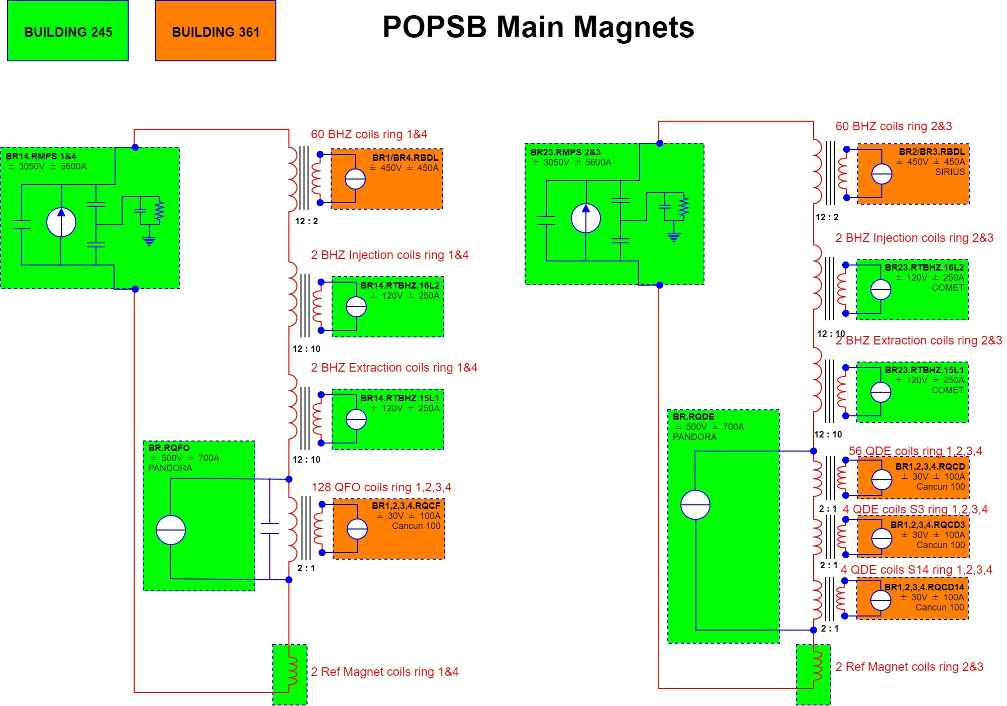
The PSB main magnets are powered by 28 power converters following the schematic represented in Figure 1. The fact that all circuits are magnetically coupled makes the control of these power converters very difficult, as any modification of one control loop has an effect on all the other circuits. This is particularly true for the Main Power Supplies (BR14.RMPS and BR23.RMPS), two 3000V 6000A power converters which generate high voltages that are coupled to all other power converters on rings 1 and 4 and rings 2 and 3 respectively, as disturbances in their respective control loops.

Figure 1: PSB main magnets and power converters
As an example, the voltage generated by one of the MPS during a 2 GeV Cycle is shown in Figure 2 as well as the influence that this has on the control scheme of the BDLs. The BDL power converters (powering the auxiliary windings of the dipole magnets) will see the voltage waveform shown in the same figure as a perturbation. As a consequence, the BDLs current controller was tuned primarily to attenuate the perturbation induced by the MPS and its performance was not optimal for this reason.
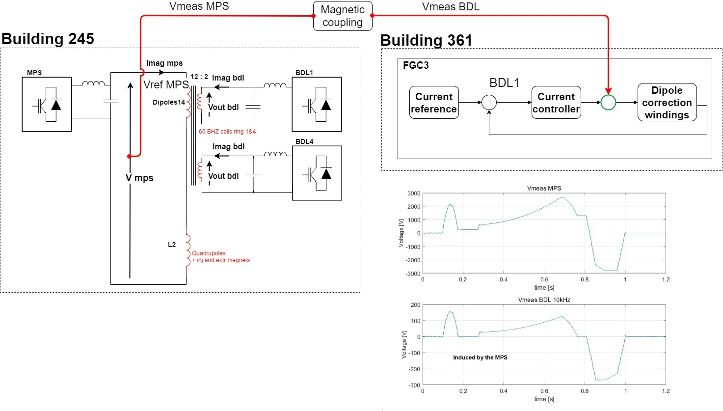
Figure 2: Reference generated by the MPS and voltage induced on the BDL
In addition, while it is normal for SY-EPC controllers to guarantee an accuracy of a few tens of parts per million (ppm) or less during the current ramps or the flat-tops, the peculiar injection scheme in the Booster requires it even during the transition between the two (see Figure 3).
In order to achieve the 80 ppm of accuracy on the peak to peak error in the magnetic field (Berr < 0.1mT peak to peak), even during the transients at the start and end of the ramp up, decoupling of the magnetic circuit was essential.
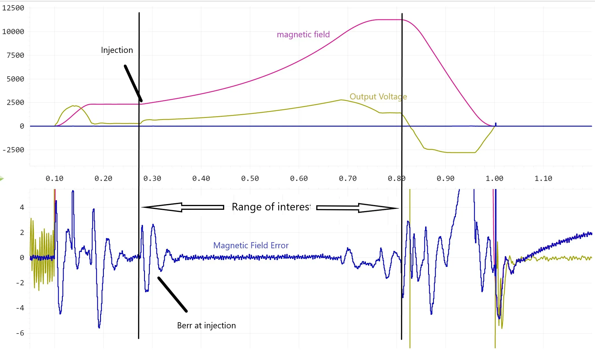
Figure 3: B-error at injection
This could be achieved thanks to the existing FGC Ethernet infrastructure (Figure 4). Using the inter-FGC communication channel was crucial to transmit the voltage reference of the MPS (Vref) to the power converter controllers of all the coupled circuits. The advantage of using the Vref instead of the measured voltage is that Vref is several milliseconds in advance of the measurement, giving the time to send the Vref value and to make some numerical manipulation with a digital filter (Figure 5) to accurately reproduce the effective perturbation seen by the coupled power converters.
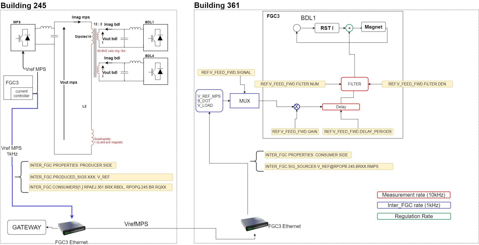
Figure 4: FGC Ether communication
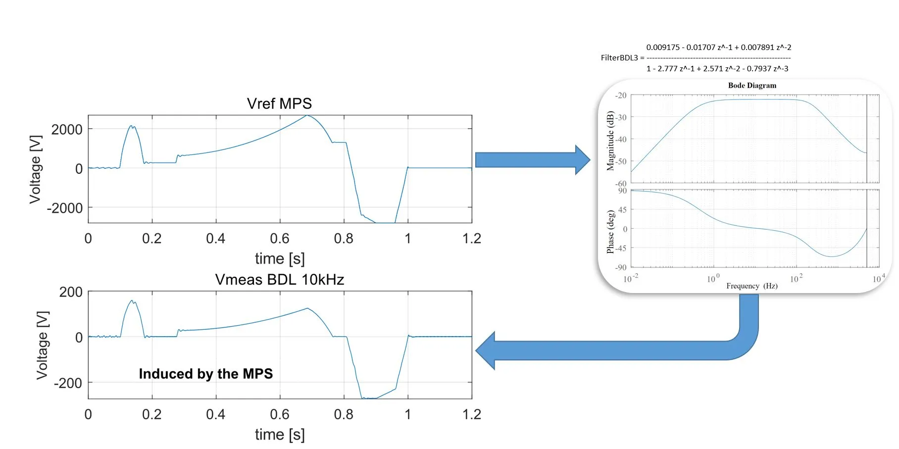
Figure 5: The Vref MPS is corrected with a numerical filter, before it is used in the Current controller
In addition, the SY-EPC Fresco tool was used to measure the frequency response of the converters and loads and to calculate the control parameters. For most of the power converters, this approach, together with the decoupling action of the Vref MPS described above, was enough to achieve the requested performances.
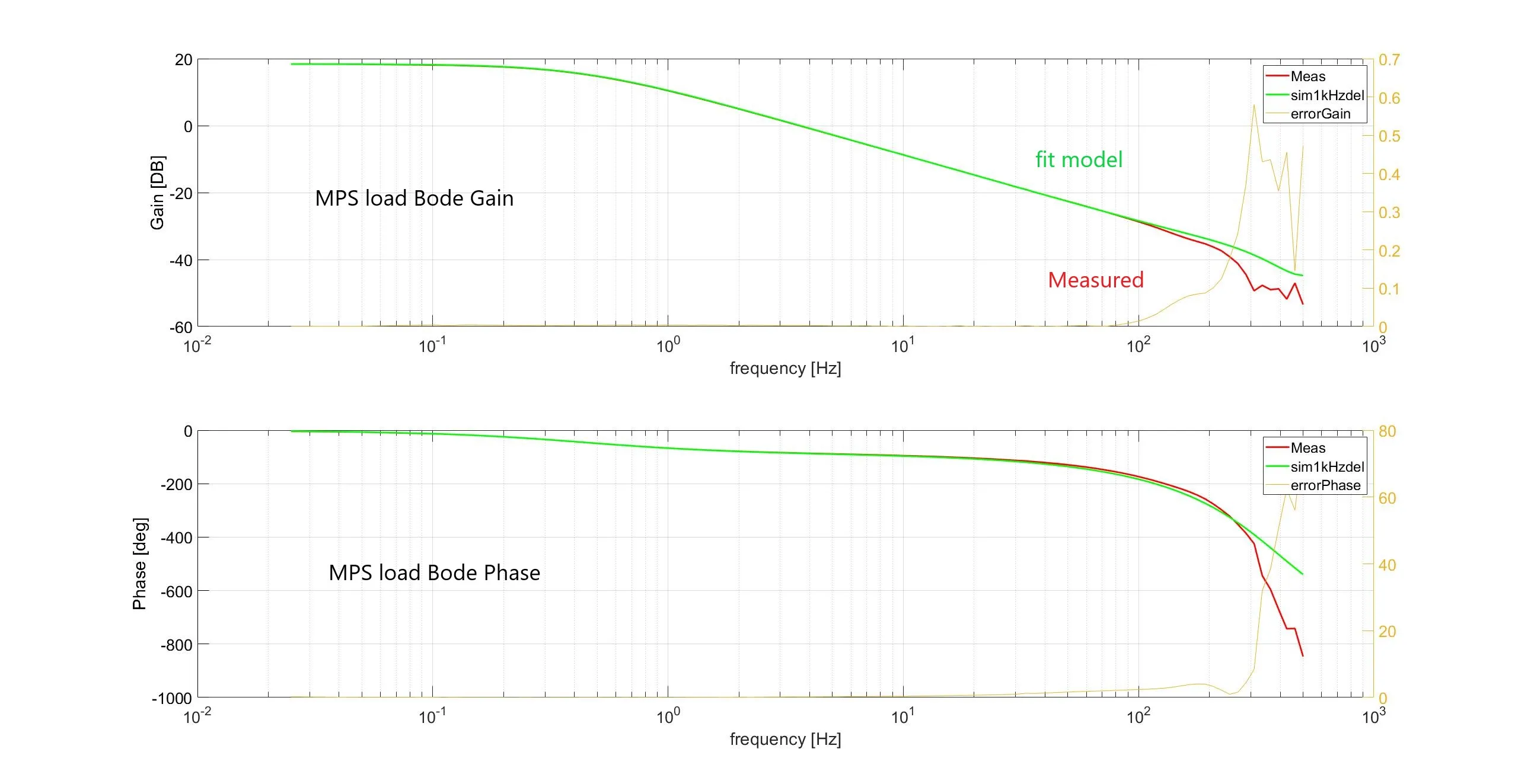
Figure 6: Frequency identification of the MPS load
Only for the MPS, given their particularly slow controller cycle times, were additional calculations necessary. To improve the magnetic field controller we used Fresco to measure the frequency response of the converter and load for each MPS (Figure 6) and then fit a discrete transfer function to the data using Matlab. Finally this model was used to calculate a suitable controller that eventually brought us to the final desired performances (Figure 7).
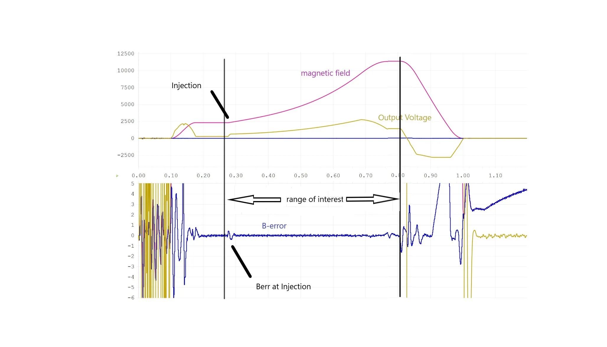
Figure 7: Berror at injection after control improvement
More than four months were needed for controller optimisation of the PS-Booster power converters. The PSB operators can now benefit from a much more precise control of the magnet fields, enabling more precise control of the accelerator tune and other vital beam parameters.
Reporting from Fulvio Boattini
Also On At CERN
-
“Warming up” of HL-LHC the power converters: first commissioning phases at the HL-LHC IT String
In the framework of the HL-LHC project, the first phases of the commissioning of the HL-LHC power converter systems of the Inner Triplet String test facility in SM18 have been successfully completed. These phases comprised the Individual System Tests (IST) and Short Circuit Tests (SCT). As a reminder, the IT String test facility aims at…
-
New power converters will soon be installed in the HL-LHC IT String
Article published in the Hilumi HL-LHC project web page August 2023 Also On At CERN
-
Successful prototype validation of ultra-high precision current measurement devices for HL-LHC
Article published in the Hilumi HL-LHC project web page MARCH 2022 Also On At CERN
-
Powering for a sustainable future
Article published in the CERN COURIER JANUARY/FEBRUARY 2022 Also On At CERN
-
Current/field control of the PS-Booster main magnets power converters
The PSB main magnets are powered by 28 power converters following the schematic represented in Figure 1. The fact that all circuits are magnetically coupled makes the control of these power converters very difficult, as any modification of one control loop has an effect on all the other circuits. This is particularly true for the…
-
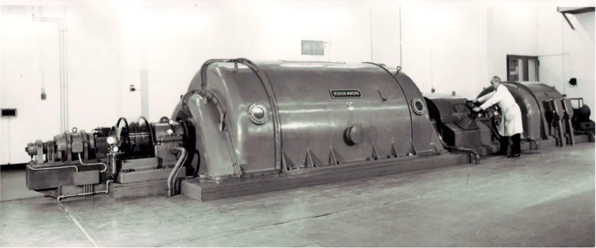
PS Main Power Supply
1959 First MPS: BBC (6kA/5.4kV) 1968 Second MPS: SIEMENS (6kA/10.8kV) Power Part simplified Architecture / Topology 2010 POPS / POwer for PS POPS supplies the PS magnets without drawing all the power from the network. The maximum stored energy in the magnets is 14MJ. This energy is supplied by the capacitor banks (CS). This exchange…
-
R2E-LHC600A-10V Power Converters
In the frame of the LHC-consolidation project, 104 radiation tolerant converters have been produced to replace the old LHC600A-10V power sources located in the irradiated areas RR1x, RR5x and RR7x. The new radiation tolerant design will solve know electrical issues (zero current crossing point) and will improve the accelerator availability thanks to a redundant design.…
-
HL-LHC2kA-10V Power Converters
HiLumi LHC project requires 36 four quadrant linear converters to trim the inner triplets magnets currents Q1 & Q3, and to power orbit correctors magnets of Q1, Q2, Q3 located in the new areas UR15 (16 units) and UR55 (16 units). A first prototype is already installed in SM18 supplying the new MCBXFA/B orbit corrector…
-
East Area Renovation 2019
In the framework of the consolidation program, the East Experimental Area has started its renovation process, during the Long Shutdown #2. The main objective is to refurbish the building 251 completely to host 64 new power converters that will power the new test area once the renovation is finished. 1. The notorious “Selecteur de ligne”…
-
GPS & REX Consolidation 2018
In the framework of the consolidation program, one power converter used for the ISOLDE GPS line (for separator magnet) and three power converters used in REX-ISOLDE (for 1x separator magnet and 2x steering magnets) have been replaced.This upgrade allows the replacement of ageing power converters and the FGC3 controller implementation with the new class 63,…